CAREER: Adaptive Power Management for Supercapacitor-Operated Sustainable Wireless Sensor Networks
Project Description
Supercapacitor Characteristics and Their Impact on Power Management
Many wireless sensor network (WSN) applications would benefit from extremely long life without physical human maintenance. Examples include structural health monitoring, environmental monitoring, biomonitoring, human health monitoring and surveillance. To extend system life time and ensure sustainability, ambient energy has been harvested to power WSNs. Various rechargeable batteries such as NiMH and Li-ion have been used as energy buffers for these energy harvesting wireless sensors. While rechargeable batteries have high capacity and low leakage rate, the cycle life (<1000) and a short life span (a few years) of rechargeable batteries limit the lifetime of wireless sensor nodes. Alternatively, Supercapacitors (SCs) have cycle lives on the order of millions and a life span of 20 years or more. Recent advances in SC technology may lead to a paradigm shift from a battery-based to a SC-based design if the adaptive power management can be established to maintain the sustainability of the WSNs, which will generate great interest from many long-life applications.
SC-based designs impose a major challenge: the energy leakage due to charge redistribution and self-discharge. The current power management strategies either neglect SC characteristics or only consider the SC self-discharge. However, our investigation demonstrates that internal charge redistribution may lead to significant larger SC terminal voltage change compared with self-discharge, as shown in Fig. 1. This indicates that SC charge redistribution may have more significant impact on power management than self-discharge.
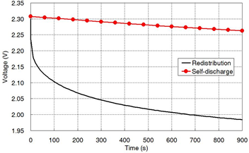
Figure 1.Comparison between the effects of charge redistribution and self-discharge.
Supercapacitor Modeling
To investigate how SC characteristics may impact power management strategies, we develop a variable leakage resistance (VLR) model that can accurately characterize the SC behavior during frequent charging-discharging cycles. The VLR model, shown in Fig. 2, is composed of three branches. The first branch has three components: , a constant capacitor
, and a voltage dependent capacitor
. The total capacitance of the first branch is
. This branch models the voltage dependency of capacitance. The time constant is on the order of seconds. The second branch includes
and
. This branch models charge redistribution with a time constant of minutes. The variable resistor
is used to model the time varying self-discharge, which is modeled as a function of the SC terminal voltage. This model can accurately capture the dynamic behavior of a supercapacitor during frequent charge-discharge cycles, as shown in Fig. 3.
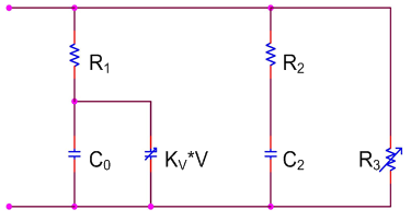
Figure 2.The variable leakage resistance (VLR) model.
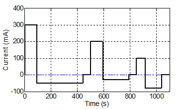
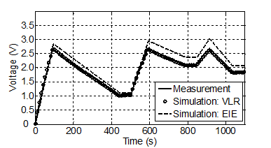
Figure 3.A dynamic test of a 10 F supercapacitor: test current profile(top); and comparison between measured and simulated terminal voltages(bottom).
Supercapacitor Energy Loss Due To Different Leakage Mechanisms
In an energy harvesting wireless sensor node, the voltages and
across the capacitors
and
in Fig. 2 may be different due to different time constants right after a charging or discharging process. The charge stored in a SC tends to redistribute among different branches, which changes the SC terminal voltage. When currents flow through the resistors in the model during charge redistribution, some electric energy is lost due to heat dissipation. The dissipated power due to charge redistribution may be more significant that that due to self-discharge at the beginning of the charge-redistribution period. For example, if
and
for a 10 F SC right after a charging process, the currents flowing through three resistors in Fig. 2 due to charge redistribution and self-discharge are shown in Fig. 4. Since
and
, the dissipated power of
is negligible. The dissipated power of
due to charge redistribution is compared with the dissipated power of
due to self-discharge, shown in Fig. 5. The results demonstrate that the energy loss is mainly contributed by charge redistribution during the initial period and by self-discharge for a relatively long term.
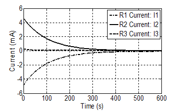
Figure 4.The VLR resistor current for initial state: and
.
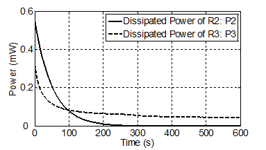
Figure 5.The dissipated power of and
for initial state:
and
.
Impact of Supercapacitor Charge Redistribution on Power Management
We have designed two scenarios to demonstrate the effects of charge redistribution of the SC storage device on the optimal scheduling policy. The results show that the optimal scheduling policy is affected by the state of the SC.
A simple SC-powered energy harvesting sensor node is used for the demonstration. The SC only operates if its terminal voltage is greater than a threshold value of 1 V. In the first scenario, a short harvested energy results in initial voltages across capacitors and
in the SC model as
and
at
. A task needs to be scheduled. The task is a current pulse defined by three parameters: amplitude 80 mA, duration 10 s, and deadline 300 s. The performance of both greedy scheduling and lazy scheduling is compared. The greedy policy schedules the task aggressively. As long as the SC voltage is above the threshold, the task is scheduled. In this scenario, the task is scheduled between 0-10 s. The lazy scheduling policy works in the opposite way. The task is only scheduled when the deadline is approaching, which is between 290-300 s.
We have evaluated both scheduling policies in terms of two metrics: success of task execution and energy loss. A successful task execution requires that the SC terminal voltage is greater than the threshold 1 V during the task execution period. As shown in Fig. 6, the SC terminal voltage after task execution is 1.10 V () and 0.97 V (
)for the greedy and lazy scheduling policies, respectively. Therefore, the greedy policy results in a successful execution of the task and the lazy policy fails. The unsuccessful execution of the lazy scheduling policy is due to charge redistribution. The task current pulse is mainly drawn from the first branch because of its much smaller time constant. For the lazy scheduling policy, charge is transferred from the first branch to the second branch during 0-290 s and there is no enough charge stored in
to support the task.
The dissipated power due to resistors and
is shown in Fig. 7. The greedy schedule results in smaller
than the lazy schedule does. For the greedy policy,
is reduced after executing the task. The voltage difference between
and
is also reduced, which results in a smaller dissipated power for
. As shown in Fig. 7(b), the dissipated power
can be neglected. Note the unit of dissipated power is µW in Fig. 7(b), and mW in Fig. 7(a).
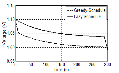
Figure 6.The supercapacitor terminal voltage during task scheduleing simulation.
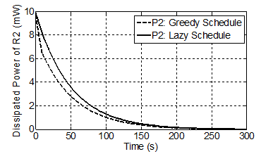
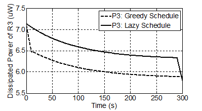
Figure 7.The dissipated power of resistors (a) and
(b) during task scheduling simulation.
The second scenario is designed to demonstrate that the lazy schedule sometimes performs better than the greedy schedule. In this scenario, a quick load discharge process leads to a SC initial state with and
at
. Fig. 8(a) shows that the task execution is unsuccessful when the task is scheduled using the greedy policy. On the other hand, the task can be successfully executed if the lazy policy is applied since part of the charge in
is redistributed to
. Fig. 8(b) shows the dissipated power of
, which is the major contributor to energy loss during the simulation period. The dissipated power of the lazy schedule is smaller. This is because
is further reduced after the task execution when the greedy policy is adopted, which increases the voltage difference between the first and second branches. The energy loss due to charge redistribution is increased.
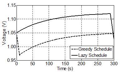
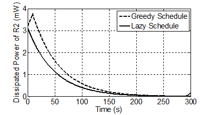
Figure 8.Simulation results of the second scenario with SC initial state: and
: (a) SC terminal voltage; (b) Dissipated power of
.

